

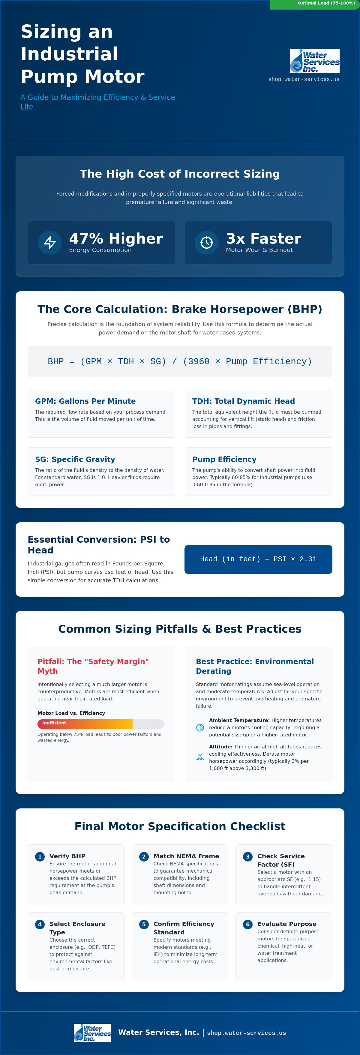
Forced modifications to standard pumps can lead to 47% higher energy consumption and three times faster motor wear. You likely already recognize that an incorrectly specified motor is an operational liability that causes frequent burnout and excessive energy waste. Mastering how to size a pump motor for industrial applications requires a precise balance of hydraulic demand, mechanical mounting, and environmental derating factors. It is the difference between a system that fails prematurely and one that maintains peak performance for its entire service life.
This 2026 guide provides the technical calculations and selection criteria you need to pair the correct industrial motor with your pumping system for maximum efficiency. We will examine the new ANSI/HI 9.6.1-2024 NPSH margin methods, IE4 efficiency standards, and NEMA frame compatibility requirements. You'll learn how to navigate complex environmental factors and ensure mechanical alignment with existing housings. By applying these specialized metrics, you can reduce operational downtime and optimize energy costs through precise motor sizing.
Key Takeaways
- Identify why excessive motor capacity creates energy waste and reduces operational efficiency in high-demand systems.
- Execute technical calculations for Brake Horsepower (BHP) based on precise Gallons Per Minute (GPM) and Total Dynamic Head (TDH) metrics.
- Verify mechanical compatibility using NEMA frame specifications and Service Factor (SF) ratings to handle intermittent system overloads.
- Master how to size a pump motor for industrial applications by accounting for environmental derating factors such as altitude and ambient cooling capacity.
- Evaluate definite purpose motor features to ensure long-term durability in specialized chemical or water treatment environments.
Understanding the Relationship Between Pump Demand and Motor Output
The motor serves as the prime mover in any industrial hydraulic system. It's responsible for converting electrical energy into the mechanical torque required to rotate the pump impeller or drive the piston. Understanding how to size a pump motor for industrial applications starts with recognizing that the motor must meet the peak demand of the pump across its entire operating range. It isn't just about the average flow; it's about the maximum load point on the performance curve.
A common error in procurement is the "sizing up" strategy. Engineers often select a motor one or two sizes larger than necessary to create a "safety margin." This approach is counterproductive. Motors are most efficient when operating between 75% and 100% of their rated load. Running a motor at significantly lower loads leads to poor power factors and increased energy costs. It also increases the initial capital expenditure without providing any mechanical benefit to the system.
You must distinguish between nominal nameplate horsepower and Brake Horsepower (BHP). The nominal rating is the motor's maximum continuous output capacity under standard conditions. BHP is the actual power the pump requires at a specific flow and head. Consider these factors when evaluating power demand:
- System Fluctuations: Clogged filters or valve adjustments change the load.
- Operating Range: The motor must cover the entire pump curve, not just the best efficiency point.
-
Mechanical Losses:
Calculating Brake Horsepower (BHP) and Total Dynamic Head (TDH)
Precise calculation is the foundation of system reliability. Mastering how to size a pump motor for industrial applications requires a strict adherence to mathematical models rather than guesswork. You must first establish the required Flow Rate in Gallons Per Minute (GPM) based on your process demand. Once the flow is defined, calculate the Total Dynamic Head (TDH) in feet of water. TDH is the sum of static head and friction loss. Static head is the vertical distance the fluid must travel, while friction loss accounts for the resistance within pipes, valves, and fittings.
The third step involves factoring in the pump’s hydraulic efficiency. Most industrial centrifugal pumps operate between 60% and 85% efficiency. Standard industry practices outlined in Pump Driver and Motor Selection emphasize that motor sizing must account for the maximum load the pump can impose, which often occurs at the end of the performance curve. Finally, apply the standard Brake Horsepower formula to determine the actual power demand on the motor shaft.
The Essential BHP Formula for Water Systems
To calculate the power required, use the following formula: BHP = (GPM x TDH x Specific Gravity) / (3960 x Pump Efficiency). The constant 3960 converts the units of flow and head into horsepower. Specific Gravity (SG) is a critical variable; for water at standard temperature, the SG is 1.0. If you're pumping heavier fluids like brine or chemical slurries, the SG will be higher, directly increasing the required BHP. You can find precise efficiency ratings on a Goulds Water Technology Pump curve, which maps out how efficiency fluctuates across different flow rates. If you are upgrading an existing system, reviewing a heavy-duty industrial pump catalog helps verify if your current housing supports the required BHP.
Converting Pressure (PSI) to Head (Feet)
Industrial gauges often display pressure in PSI, but pump curves use feet of head. To convert, multiply the PSI by 2.31. This 2.31 conversion factor is essential for calculating the TDH accurately in piping networks. For example, a system requiring 50 PSI needs 115.5 feet of head. You must also distinguish between suction lift and flooded suction scenarios. In suction lift, the pump is above the fluid source, adding to the total head. In flooded suction, the fluid level is above the pump, which provides a positive suction pressure that reduces the total work the motor must perform. Accurate friction loss calculations for your specific pipe diameter and material are mandatory to prevent undersizing the motor.
Evaluating Motor Specifications: NEMA Frames, Enclosures, and Service Factors
Determining the correct horsepower is only the first stage of procurement. To fully master how to size a pump motor for industrial applications, you must ensure the physical assembly and environmental protection match the installation site. National Electrical Manufacturers Association (NEMA) standards provide the framework for these specifications. These standards ensure that a motor from one manufacturer will physically fit the mounting of a pump from another, provided the frame sizes align. If you ignore these physical dimensions, you risk costly field modifications or complete mechanical incompatibility.
Service Factor (SF) is a critical metric for handling intermittent overloads. An SF of 1.15 means the motor can handle 15% more than its rated horsepower for short periods. However, relying on the service factor for continuous operation is a poor engineering practice. It leads to excessive heat and insulation breakdown. For 2026 industrial standards, Class F or Class H insulation is the benchmark. These materials withstand higher internal temperatures, which is vital when operating near the motor's thermal limits. High-quality insulation directly correlates to the motor's longevity in high-cycle environments.
NEMA Frame and Mounting Configurations
Physical dimensions are dictated by frame numbers like 56C or 143T. The "C" suffix indicates a C-Face motor, where the pump bolts directly to the motor face. D-Flange motors use a different mounting flange that extends beyond the motor body. Consult University of Toledo Engineering Resources for access to comprehensive mechanical engineering handbooks that detail these specific dimensional standards. Matching shaft diameter and length is mandatory for direct-coupled systems to prevent vibration and bearing failure. Even a minor misalignment in shaft height can cause premature seal failure in centrifugal pumps.
Choosing the Right Enclosure for Harsh Sites
Environmental protection is defined by the enclosure type. Totally Enclosed Fan Cooled (TEFC) units are the industrial standard for sites with dust, moisture, or chemical exposure. They use an external fan to blow air over the motor ribs without exchanging internal and external air. In contrast, Open Drip Proof (ODP) motors allow air to flow through the windings. These are suitable for clean, indoor commercial water systems where environmental contaminants are minimal. For volatile environments involving gas or oil, explosion-proof ratings are required to prevent internal sparks from igniting the atmosphere. Selecting the wrong enclosure can lead to immediate motor burnout if debris enters the internal windings.
Avoiding Common Sizing Pitfalls and Environmental Derating
Industrial procurement often falls into the trap of over-specification. The "Bigger is Better" mindset is a primary cause of system inefficiency. An oversized motor does not provide a safety net; instead, it operates at a significantly reduced power factor and lower efficiency. This results in higher utility costs and increased reactive power charges. When you investigate how to size a pump motor for industrial applications, you must prioritize the motor's Best Efficiency Point (BEP). Selecting a motor that matches the pump's peak BHP requirement without excessive headroom ensures the mechanical components, such as couplings and bearings, are not subjected to unnecessary torque during startup.
Oversizing also complicates the electrical infrastructure. Larger motors require heavier gauge wiring, larger contactors, and more robust circuit protection. These components add unnecessary capital costs to the project. If the motor is too large for the pump's demand, it may never reach its design operating temperature. This can lead to moisture accumulation in the windings in humid environments, eventually causing a short circuit. Precision in sizing protects both the electrical and mechanical integrity of the station.
Environmental Derating Factors for Remote Operations
Standard motor ratings assume an altitude below 3,300 feet (1,000 meters) and an ambient temperature of 104°F (40°C). In mining or high-altitude chemical processing, the thinner air has a lower heat-carrying capacity. This reduces the effectiveness of the cooling fan in TEFC motors. For every 330 feet above the 3,300-foot threshold, you must typically derate the motor's output by 1%. Similarly, ambient temperatures exceeding 104°F require a reduction in the allowable load to prevent thermal runaway. Excessive heat reduces the dielectric strength of motor windings, leading to premature insulation failure. Failure to account for these site-specific variables will lead to frequent thermal tripping and winding burnout.
VFD-Ready Motors: The 2026 Efficiency Standard
Modern industrial systems require flexibility. Sizing a motor for the "worst-case" hydraulic flow is a technical necessity, but running at that peak 100% of the time is rarely efficient. You should use a Variable Frequency Drive (VFD) to modulate motor speed based on real-time demand. However, not all motors are compatible with VFDs. Inverter-duty motors must feature corona-resistant wire and enhanced insulation to withstand the high-voltage spikes generated by the drive's pulse-width modulation. Pair your motor with electric power controls to ensure the drive and motor operate in synchronization. This setup allows for soft-starting, which eliminates the mechanical shock of across-the-line starting. To maintain system integrity, select compatible VFD and control systems that match your motor's voltage and current ratings.
Selecting the Right Definite Purpose Motor for Your System
Matching the motor RPM to the pump's design speed is a non-negotiable step. Most industrial centrifugal pumps are designed for either 1800 RPM (4-pole) or 3600 RPM (2-pole) operation. Using a 3600 RPM motor on a pump designed for 1800 RPM will cause immediate mechanical failure and potential safety hazards. It's a risk that's easily avoided by checking the pump nameplate before finalizing your motor selection. Conversely, running a high-speed pump with a low-speed motor results in a failure to meet the required head and flow, rendering the entire system ineffective.
Top Picks from Our Definite Purpose Collection
Selecting the correct motor depends on the operational environment and the fluid being managed. Premium efficient motors are the standard for continuous-duty industrial water treatment systems where energy consumption is a primary concern. For facilities requiring frequent sanitization, such as food-grade or chemical processing, washdown-duty motors provide the necessary sealing against high-pressure sprays. In agricultural or municipal settings, vertical hollow shaft motors are the preferred choice for deep well turbine applications. They allow for easy adjustment of the pump impellers and handle the high down-thrust loads typical of deep-well extraction. Understanding how to size a pump motor for industrial applications means matching these physical configurations to your site requirements.
Final Procurement Checklist
Before completing your order, verify the electrical and mechanical specifications one final time. Incompatibility at this stage leads to expensive returns and project delays. Use this checklist to ensure a successful installation:
- Voltage and Phase: Confirm if the site provides 230/460V and whether you require a single-phase or three-phase configuration.
- Rotation Direction: Determine if the pump requires Clockwise (CW) or Counter-Clockwise (CCW) rotation when viewed from the drive end.
- Frame Size: Re-verify the NEMA frame dimensions to ensure the shaft height and mounting holes align with your existing pump housing.
- Enclosure Rating: Ensure the TEFC or ODP rating matches the environmental conditions discussed in previous sections to prevent internal winding damage.
Technical precision in procurement prevents operational failure and extends the life of your equipment. Browse our full range of Definite Purpose Motors to find your exact match and secure your system's long-term reliability.
Securing Your Industrial Hydraulic Infrastructure
Implementing the technical standards discussed in this guide is the most effective way to eliminate operational downtime. Precise motor selection prevents the frequent burnout caused by undersizing and the extreme energy waste of oversized units. Mastering how to size a pump motor for industrial applications ensures your facility avoids the 47% increase in energy consumption often caused by forced modifications. This technical diligence guarantees your system meets 2026 efficiency standards while maintaining peak performance in demanding environments; similarly, those looking for precision in other mechanical systems can discover Drive Systems USA for high-performance motorcycle drivetrain components.
We are an authorized distributor of Goulds Water Technology, providing specialized engineering support for mining and military operations. Our logistical network supports global shipping to Africa, South America, and the Middle East. You can rely on our technical expertise to ensure your motor and pump housing are perfectly paired for long-term service. Shop the Definite Purpose Motors Collection today to find the exact specifications for your application. Your system's reliability depends on precise engineering.
Frequently Asked Questions
How do I calculate motor horsepower if I only know PSI and GPM?
You can calculate the required power using the formula: HP = (GPM x PSI) / (1714 x Pump Efficiency). While the standard formula uses feet of head, this version allows for direct input from industrial pressure gauges. You must include the pump's efficiency rating, typically between 0.60 and 0.85, to ensure the motor provides enough torque to overcome mechanical and hydraulic losses within the system.
What is the difference between a 56C and a 145T frame motor?
The primary difference lies in the mounting interface and shaft dimensions. A 56C frame features a C-Face flange for direct bolting to a pump, while a 145T frame is a standard T-frame that may or may not have a mounting flange. Although both have a 3.5 inch shaft height, their shaft diameters and lengths differ. You must verify the pump’s bracket requirements to ensure a precise mechanical fit.
Can I use a 3600 RPM motor on a pump designed for 1800 RPM?
No, you cannot swap these speeds without causing catastrophic mechanical failure. Centrifugal pump power requirements follow the Affinity Laws, meaning power demand increases by the cube of the speed. Doubling the RPM from 1800 to 3600 would require eight times the horsepower. This mismatch will lead to immediate motor burnout, seal failure, or impeller damage due to excessive centrifugal force.
What does a 1.15 Service Factor mean for my industrial application?
A 1.15 Service Factor (SF) indicates the motor can handle a continuous overload of 15% beyond its rated horsepower under standard conditions. It acts as a safety margin for intermittent load spikes or minor voltage fluctuations. However, you shouldn't rely on the SF for daily operation. Running a motor in its service factor range increases internal heat, which significantly shortens the lifespan of the winding insulation.
When should I choose a TEFC motor over an ODP motor?
Choose a Totally Enclosed Fan Cooled (TEFC) motor for any environment containing dust, moisture, or chemical vapors. TEFC units prevent outside air from entering the motor, using an external fan for cooling. Open Drip Proof (ODP) motors are only suitable for clean, dry, indoor locations. Using an ODP motor in a washdown or outdoor area will lead to rapid internal corrosion and electrical shorts.
How does high altitude affect my pump motor sizing?
High altitude requires motor derating because the thinner air provides less effective cooling for the internal components. When learning how to size a pump motor for industrial applications at elevations above 3,300 feet, you must reduce the allowable load or select a larger motor. This prevents thermal tripping in regions where the air density is insufficient to carry away the heat generated during continuous duty cycles.
What happens if I install a motor with too much horsepower?
Installing an oversized motor leads to poor electrical efficiency and a low power factor. Your utility costs will increase because the motor consumes more reactive power than necessary for the work performed. Additionally, if the motor doesn't reach its design operating temperature, moisture can accumulate in the windings. This is a common pitfall when professionals overlook the specific metrics of how to size a pump motor for industrial applications.
Are all Goulds Water Technology pumps compatible with NEMA motors?
Most industrial Goulds Water Technology pumps are designed to interface with standard NEMA C-face or T-frame motors. This standardization allows for easier replacement and maintenance across different motor manufacturers. However, some specialized or high-pressure models may require specific shaft extensions or D-flange mountings. You should always cross-reference the pump’s technical datasheet with the motor’s frame specification before finalizing a purchase to ensure compatibility.
0 comments